](https://deep-paper.org/en/paper/2507.08285/images/cover.png)
Imagine you have a photo of a person looking to the left, and you want them to look to the right. With modern Generative AI, specifically “drag-based” editing, this should be simple: you click the nose (the handle point) and drag it to the right (the target point).
In theory, the AI should understand the geometry of a face. It should know that when the nose moves, the cheek, the ear, and the hat should rotate along with it. In practice, however, current methods often fail to grasp this structural integrity. Instead of rotating the head, the AI might simply stretch the nose like taffy, distorting the face into a surrealist nightmare. This is known as the geometric inconsistency problem.
Today, we are diving deep into a research paper that proposes a clever solution to this issue: FlowDrag. This method argues that to edit 2D images accurately, we must momentarily step into the third dimension. By generating a temporary 3D mesh, deforming it using physics-based rules, and then guiding the AI with that structural information, FlowDrag achieves edits that look physically plausible and geometrically sound.
The Problem with 2D Dragging
Before we dissect the solution, we need to understand why current methods struggle.
State-of-the-art tools like DragGAN or DragDiffusion typically operate by optimizing “latent codes” (the compressed representation of the image in the AI’s brain). They use point tracking to move a specific feature (like a pixel on a nose) toward a target.
The issue is that these models often treat the image as a collection of pixels or features without understanding the underlying object structure. If you drag a point on a Statue of Liberty image, the model might move that specific point but leave the surrounding structure behind, creating a “melting” effect.
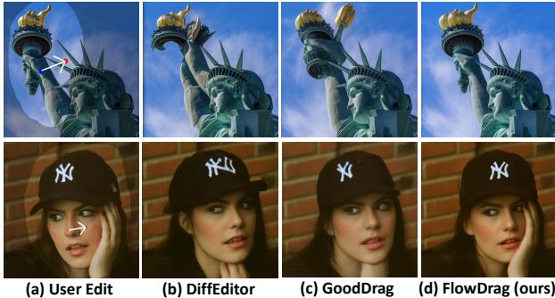
As shown in Figure 1 above, look at the first row (the Statue of Liberty). In standard “User Edit” scenarios, simply dragging the torch causes other methods (like DiffEditor or GoodDrag) to distort the arm or the crown. In contrast, FlowDrag (panel d) maintains the structural integrity of the statue. Similarly, in the second row, dragging the woman’s nose to rotate her face usually distorts her hat and hand. FlowDrag, however, rotates the entire head assembly coherently.
The FlowDrag Solution: Thinking in 3D
The core insight of the FlowDrag paper is that “Rigid Edits”—transformations like rotation, relocation, or pose changes—require a preservation of geometry that 2D feature maps just can’t provide.
To solve this, the researchers propose a pipeline that consists of three main phases:
- 3D Mesh Generation: Convert the 2D image into a 3D mesh.
- Mesh-Guided Deformation: Deform the mesh using physical constraints (making sure it bends but doesn’t break).
- Vector Flow-Based Editing: Project that 3D movement back into 2D to guide the diffusion model.
Let’s break these down step-by-step.
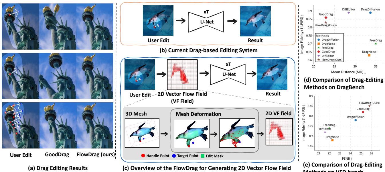
Figure 2 gives us a high-level view. Panel (b) shows the current standard: a user edit goes straight into the U-Net. Panel (c) shows the FlowDrag approach: the user edit informs a 3D Mesh, which generates a Vector Flow Field, which then guides the generation.
Step 1: Generating the 3D Mesh
You cannot deform a mesh if you don’t have one. The authors propose two approaches to lift the 2D image into 3D space:
- Depth-Based Approach (DepthMesh): They use a depth estimation model (Marigold) to guess how far away every pixel is. They map these pixels to 3D coordinates (\(x, y, z\)) and connect adjacent points to form triangles. To avoid connecting foreground objects to the background (which would create weird “curtains” of geometry), they cut connections where the depth difference is too large.
- Diffusion-Based Approach (DiffMesh): Sometimes depth maps aren’t enough because they can’t see the “back” or “side” of an object. The authors also utilize image-to-3D diffusion models (like Hunyuan3D) which can hallucinate the hidden geometry of an object, creating a more complete mesh.
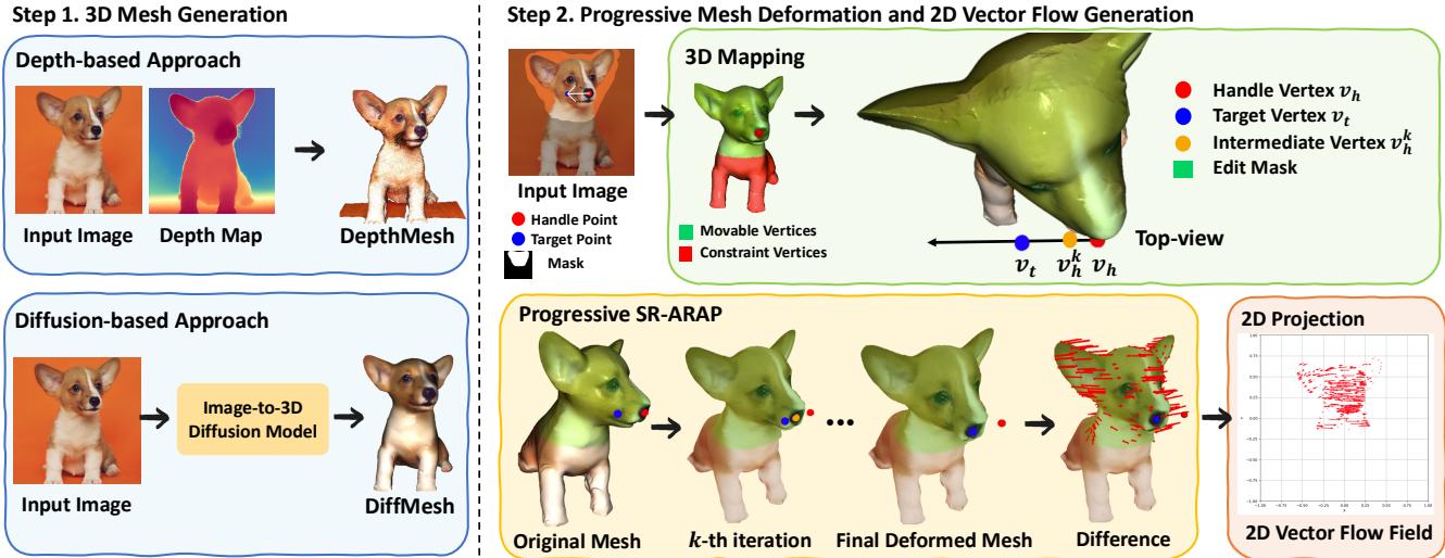
Figure 3 (Step 1) visualizes this choice. The DepthMesh is faster but essentially a relief carving. The DiffMesh provides a fuller shape, allowing for more complex rotations.
Step 2: Progressive Mesh Deformation (SR-ARAP)
Once we have a mesh, how do we move it? We can’t just teleport the “handle” vertex to the “target” vertex, or the mesh would spike and distort. We need the rest of the mesh to follow along naturally.
The authors employ a technique called As-Rigid-As-Possible (ARAP). The goal of ARAP is to move the handle points to their targets while trying to keep every triangle in the mesh the same shape and size as it was before. It minimizes the distortion (stretching or shearing) of the local geometry.
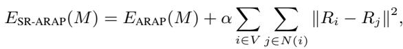
Mathematically, standard ARAP minimizes an energy function based on the rotation and position of vertices:
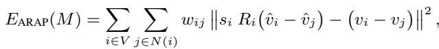
Here, \(R_i\) is a rotation matrix for vertex \(i\). The equation essentially asks: “Find the new positions \(\hat{v}\) such that the relationship between neighbors looks like the original relationship, just rotated.”
However, standard ARAP can sometimes result in jagged rotations. To fix this, the authors use Smoothed Rotation ARAP (SR-ARAP), which adds a regularization term to ensure that neighboring vertices have similar rotations:
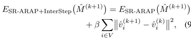
The Progressive Twist: Even with SR-ARAP, dragging a point a long distance in one go can break the mesh. The authors introduce a Progressive Deformation strategy. Instead of moving the handle point all at once, they move it in small increments (iterations).

At each step, they add an “Inter-Step Smoothness” term to the energy function, which penalizes vertices for moving too far from their position in the previous step. This ensures a smooth, stable animation from the start pose to the end pose.
Step 3: Generating the Vector Flow Field
After the mesh has been successfully deformed in 3D space, the system needs to translate this 3D change into instructions the 2D diffusion model can understand.
The authors project the original mesh and the deformed mesh back onto the 2D image plane. By comparing the position of vertices before and after the deformation, they calculate a 2D Vector Flow Field (\(\Phi\)). This field represents a map of arrows telling every part of the image exactly which direction and how far to move.

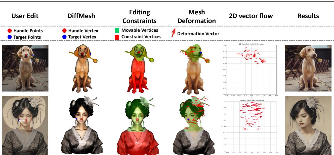
Figure 9 beautifully illustrates this process. From the user edit (top left), to the mesh constraints (green/red dots), to the deformation vectors, and finally the 2D Vector Flow field (second column from the right). Notice how the flow field captures the rotation of the entire head, not just the drag points.
Integrating Flow into Diffusion
Now comes the “Drag” part of the editing. FlowDrag integrates this vector field into the standard diffusion process (Stable Diffusion).
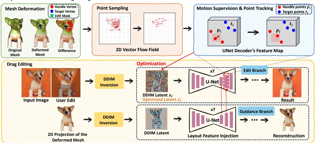
As shown in Figure 4, the architecture splits into two branches:
- Guidance Branch: This branch takes the projected 2D image of the deformed mesh and injects its layout features into the main branch. This gives the model a strong hint about the new structure (e.g., “the head is now tilted this way”).
- Edit Branch (Motion Supervision): This is where the standard drag-editing loop happens.
In standard approaches, the model searches for the handle point blindly. In FlowDrag, the Motion Supervision loss is guided by the vectors we calculated earlier.
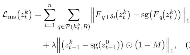
Instead of optimizing the latent code \(z_t\) based on a simple point shift, FlowDrag optimizes it so that the features move specifically along the trajectories defined by our mesh-derived flow vectors.
The latent \(z_t\) is updated via gradient descent:
Simultaneously, the handle points are tracked in the feature map to ensure they are actually landing where they are supposed to:
By combining Layout Feature Injection (giving the model the “shape”) and Vector Flow Supervision (giving the model the “movement”), FlowDrag forces the diffusion model to respect the physical rigidity of the object.
The VFD-Bench Dataset: A Better Way to Measure
One of the secondary contributions of this paper is the critique of existing benchmarks. In datasets like DragBench, there is no “Ground Truth.” You have an image and a request to “move the nose,” but no reference for what the perfect result looks like.
Metrics like LPIPS (which measures perceptual similarity) are often used to see if the image quality degraded. However, if you successfully rotate a face, the new image should look different from the original. A low similarity score might actually mean a good edit!
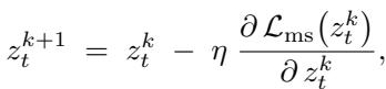
To fix this, the authors introduce VFD-Bench (Video Frame Drag Benchmark).
They utilize video sequences (Figure 5). If a video shows a cat turning its head from Frame A to Frame B, then Frame A is the “Input” and Frame B is the “Ground Truth.” The drag instruction is defined as the movement required to get from A to B.
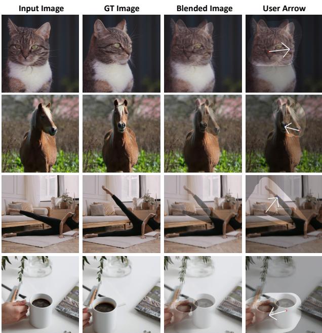
This allows for accurate measurement:
- PSNR/LPIPS: Does the edited image look like the actual next frame of the video?
- Mean Distance (MD): Did the handle points land on the target points?
Experimental Results
The authors compared FlowDrag against leading methods like DiffEditor, DragDiffusion, FreeDrag, and GoodDrag.
Qualitative Results
Visually, the difference is stark.
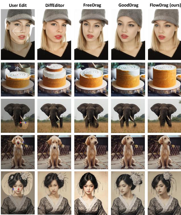
In Figure 6, look at the elephant (Row 3). The user wants to lift the trunk.
- FreeDrag and GoodDrag struggle to move the trunk coherently or introduce artifacts.
- FlowDrag lifts the trunk naturally, preserving the texture and volume.
Similarly, in the last row (woman in traditional dress), FlowDrag rotates the head while keeping the complex hair ornaments rigid and attached to the head, whereas other methods distort them.
Quantitative Results
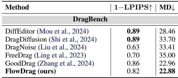
On DragBench (Table 1), FlowDrag achieves the lowest Mean Distance (MD) (22.88), meaning it is the most accurate at moving points to their targets. It also maintains high image fidelity.
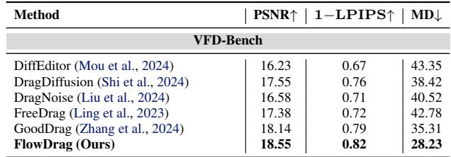
On VFD-Bench (Table 2), where ground truth is available, the results are even more conclusive. FlowDrag scores the highest PSNR (18.55) and lowest MD (28.23), proving it produces images that are both geometrically accurate and visually closest to reality.
User Study & Analysis
The researchers didn’t just trust the numbers; they asked humans too.
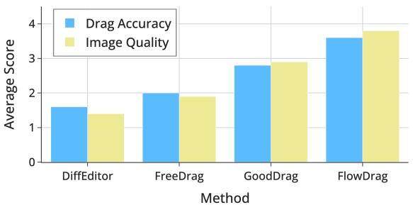
Figure 7 shows that human raters consistently scored FlowDrag higher on both “Drag Accuracy” and “Image Quality” compared to competitors.
They also analyzed how many vectors from the flow field are needed.
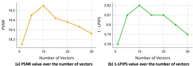
Figure 8 reveals that sampling around 10 vectors from the flow field is the “sweet spot” for maximizing Peak Signal-to-Noise Ratio (PSNR). Using too few provides insufficient guidance; using too many might over-constrain the model with conflicting information.
Robustness of Mesh Deformation
A critical question is: Does this rely too heavily on perfect meshes? What if the depth map is bad?
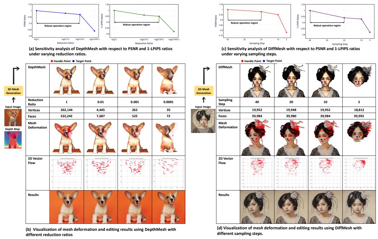
The authors performed a sensitivity analysis (Figure 15).
- Panel (a) & (b): They reduced the mesh complexity (reduction ratio) significantly. The system remained robust even when the mesh was simplified down to a ratio of 0.001.
- Panel (c) & (d): For the diffusion-based mesh (DiffMesh), they reduced the sampling steps. The editing quality remained stable even when reducing the generation steps from 40 down to 10.
This suggests that FlowDrag doesn’t need a “perfect” 3D mesh—it just needs a “good enough” mesh to capture the general geometric flow.
Conclusion
FlowDrag represents a significant step forward in AI image editing by bridging the gap between 2D generative models and 3D geometry. By explicitly modeling the “physics” of the edit via a 3D mesh—even a temporary, estimated one—the method prevents the uncanny distortions that plague pure 2D approaches.
Key takeaways:
- Geometry Matters: Pure 2D latent optimization is insufficient for rigid object manipulation.
- Mesh Guidance: Using SR-ARAP deformation on a proxy mesh provides a robust “Vector Flow Field” to guide generation.
- Better Benchmarks: Evaluating drag editing requires ground truth, which video frames (VFD-Bench) can provide.
While FlowDrag is currently optimized for rigid edits (rotations, pose changes) and relies on the quality of mesh generation, it opens the door for future work where diffusion models might innately understand 3D structures, leading to even more intuitive and realistic creative tools.